The Explanation of Low Energy Nuclear Reaction
An Examination of the Relationship Between Observation and ExplanationProgress Report #2
This report describes how a Seebeck calorimeter is calibrated in order to measure the amount of excess power produced by a cathode in an electrolytic cell contained in the calorimeter and the expected uncertainty in this value.
PROGRESS-REPORT-2 (3.5Mb)
A Seebeck calorimeter uses thermoelectric converters (TEC) to create a voltage proportional to the rate at which heat energy leaves the calorimeter. The present design consists of a water-cooled aluminum box with TEC covering the inside of each surface.
Consequently, the amount of heat energy leaving the box is measured regardless of where this loss takes place. A calibration using a known source of heat energy is required to calibrate the device.
Two different methods are used to apply known heat energy, with several variations involving the electrolytic cell or resistors external to the cell. Electric power can be supplied to the electrolytic cell containing a platinum cathode, which is presumed to produce no excess energy. Or electric power can be applied to a glass covered internal resistor located in the electrolyte, as can be seen in Fig. 1.
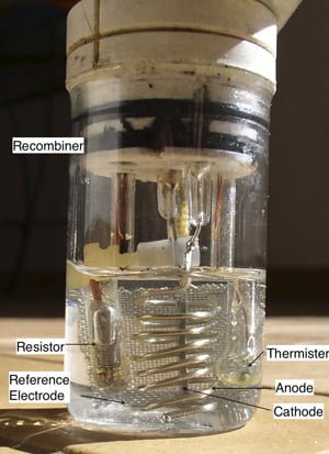 FIGURE 1. Pyrex electrolytic cell. The electrolytic cell consists of a cathode and anode and the internal resistor consists of a coil of nichrom wire immersed in oil contained in a thin wall Pyrex tube.
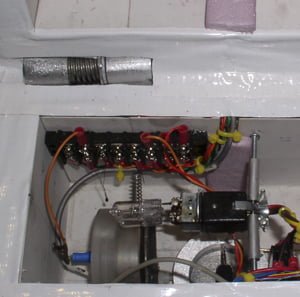 FIGURE 2. Picture of the two small quartz light bulbs used for calibration. One is connected to the circuit providing power to the anode and cathode and the other is connected to the circuit supplying power to the resistor contained in the Pyrex cell, which is removed for this test.
Read more in PROGRESS-REPORT-2 (3.5Mb)
See also:
| August 13th, 2015 | Posted in Science |